A lot of companies say they want to operationalize AI, but their job descriptions often reveal a different truth. They keep hiring for another Lead ML Engineer, even though the real bottleneck is rarely model research.
This article explores why that hiring pattern is often low ROI for large enterprises, and what a more practical production path actually looks like.
Why Most Enterprises Do Not Need Another Lead ML Engineer
Foundation models keep improving, and models are getting faster, more knowledgeable, and more capable. For most enterprises, the old logic is gone. A model edge no longer stays fresh for 10 to 20 years. In many cases, it does not even last 10 to 20 months. It can become legacy in 10 to 20 weeks.
That makes the real enterprise problem very different. The bottleneck is no longer model capability in isolation. It is how AI is governed, integrated, and operated once it enters real products and workflows.
The moment AI leaves a demo and starts spreading across real products, new problems show up very quickly. Retrieval has to be scoped. Prompts have to be versioned. Outputs need contracts. APIs need to be stable. Changes need approval. Runs need audit trails. And once multiple workflows, teams, or workspaces are involved, the question is no longer “how do we call a model?” but “how do we stop AI behavior from fragmenting across the business?”
When AI Automation Turns into a Governance Problem
I ran into exactly that problem while building AI automation products across multiple domains. At first, the wins were obvious. It was easy to automate specific tasks and get value quickly. But once the number of products, workflows, and use cases started growing, the shape of the problem changed completely.
Retrieval, prompts, outputs, approvals, APIs, and collaboration were starting to turn into separate, inconsistent, and increasingly messy implementations across products.
That was when I stopped thinking about another AI app and started building a governed multi-tenant applied AI platform instead.
So instead of building another isolated AI app, I built this.
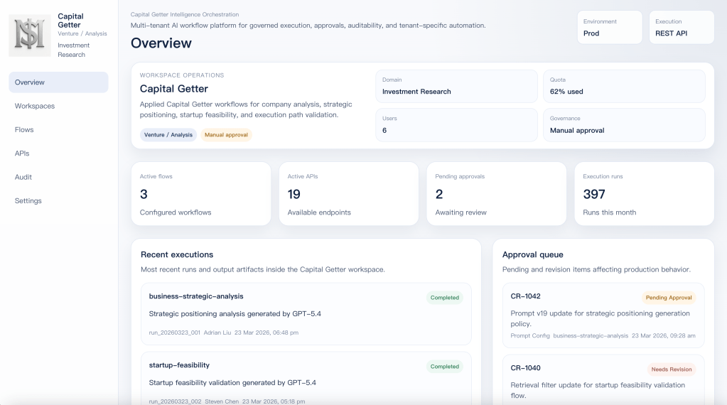
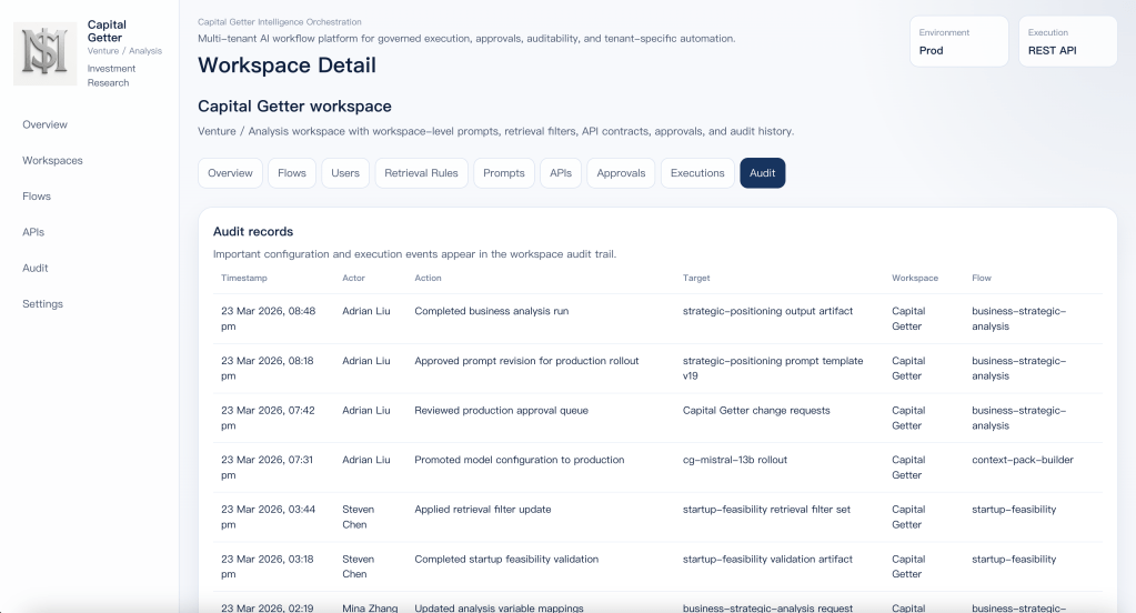
This is the control panel of a governed applied AI workspace.
It runs under quota, approval, audit, and production API contracts. AI here is not something you just invoke once and forget. It has to be operated, reviewed, and kept inside clear boundaries.
It runs as a reusable workspace on top of a shared execution platform. Capital Getter keeps its own prompts, retrieval rules, flows, output contracts, approvals, and audit trail without needing its own separate platform stack.
That separation is the whole point. The platform capability is shared. The business behavior of the workspace is not.
Once I reached this point, the question changed. It was no longer “how do I call a model?” It became “how do I define, govern, and evolve AI execution without forcing every product to rebuild its own workflows, control layer, and approval path from scratch?”
That is the real production question behind enterprise applied AI.
How the system works in practice
The answer was not another isolated AI feature.
The answer is a governed system built around flows, prompts, API contracts, approvals, and audit.
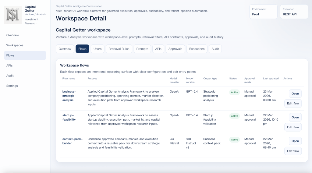
Flow catalog for workspace-specific execution paths
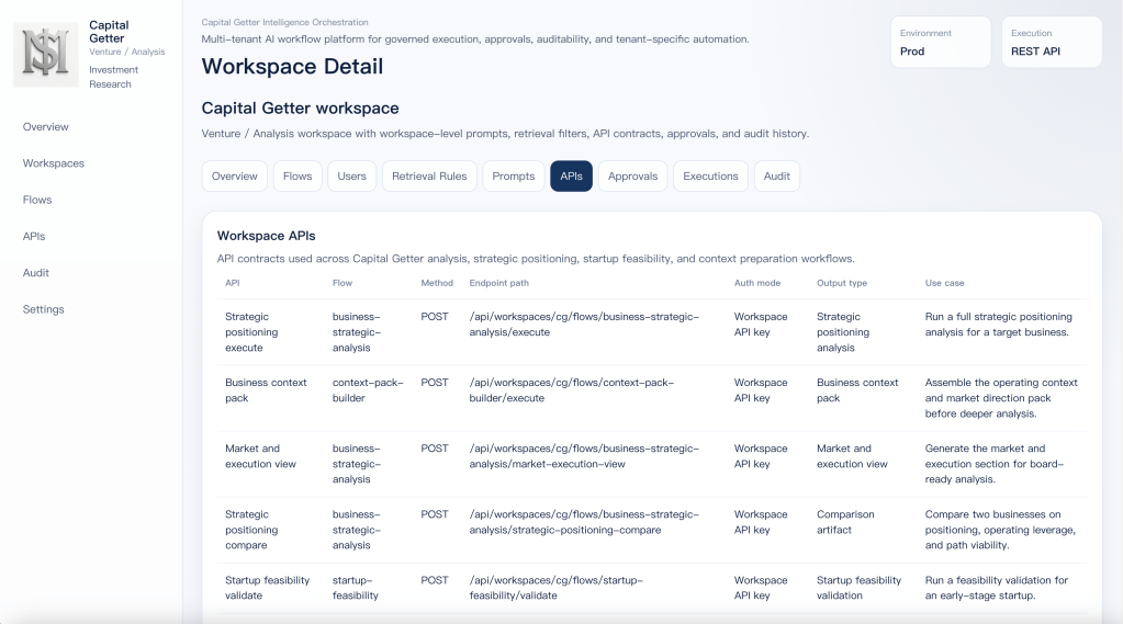
Workspace API contracts for applied business workflows
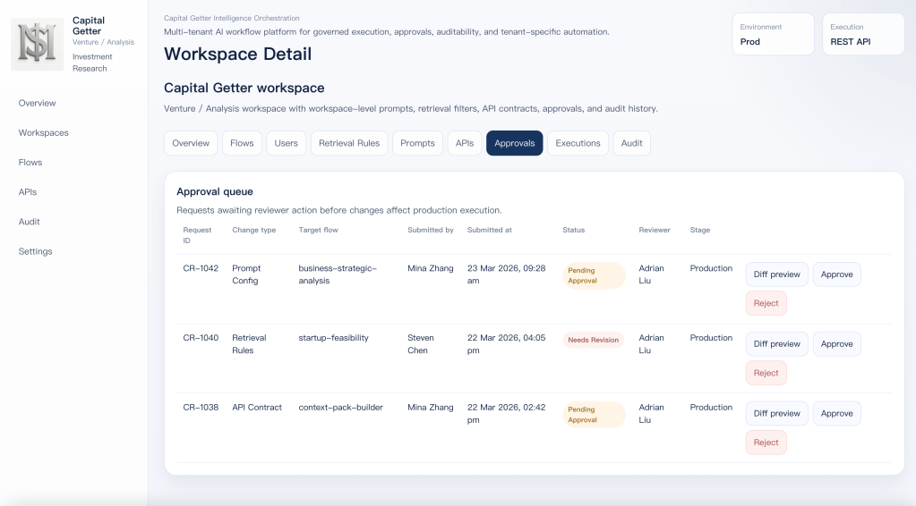
Approval queue for governed changes
Audit trail for configuration, execution, and rollout tracking
What actually runs underneath it
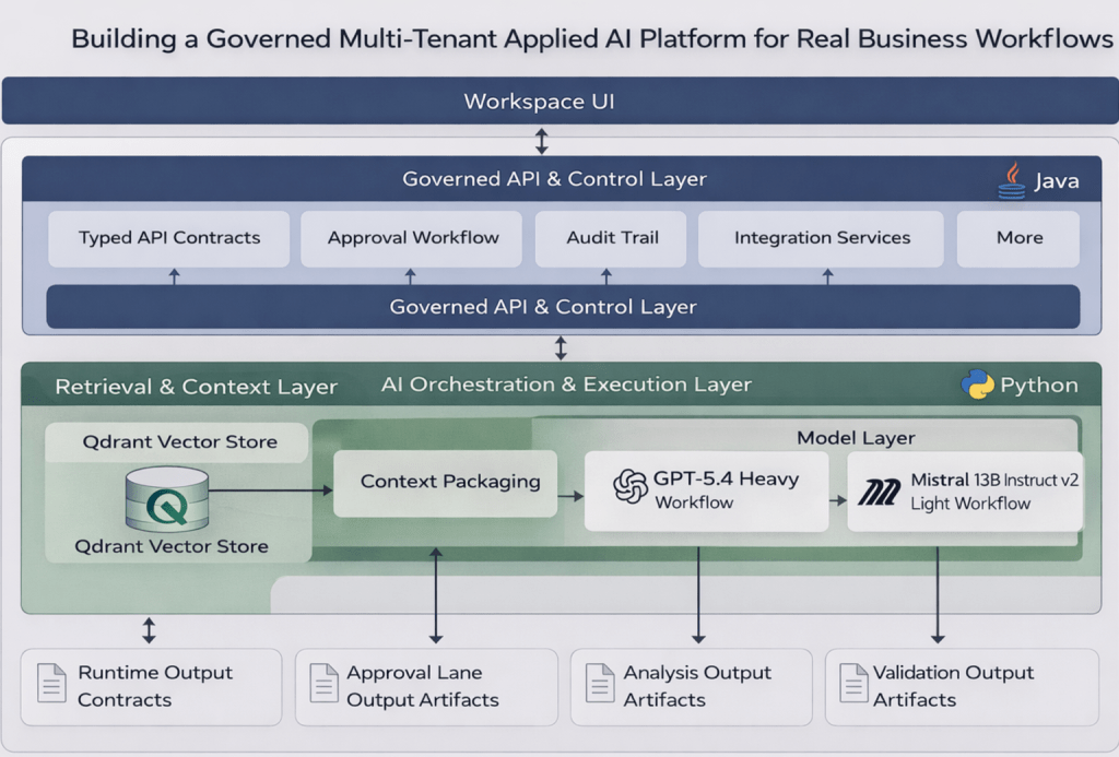
RAG is the first real layer underneath the UI. In this system, it is the workspace-specific context layer. Each flow defines its own retrieval scope, collection boundaries, categories, tags, and context packaging rules before anything reaches the model.
Qdrant sits underneath that retrieval layer as the vector store, but vector search alone is not the point. The value comes from controlled context selection. The system has to retrieve the right business context for the right workflow, inside the right boundary, before generation even begins.
LangChain is used as the orchestration layer. It coordinates retrieval, prompt assembly, variable injection, model invocation, and output shaping. The business rules do not live in LangChain itself. They live in the workflow definitions, API contracts, approval rules, and workspace configuration above it.
The runtime is also split by role. Java handles the stable system boundary: typed API contracts, approval flow, audit events, and integration-facing services. Python handles the faster-moving AI layer: retrieval pipelines, LangChain orchestration, prompt assembly, and model execution. The split is there to separate governed system behavior from faster iteration in AI workflows.
Model choice follows workflow weight. Heavier flows such as business-strategic-analysis and startup-feasibility use GPT-5.4 because they need deeper synthesis across larger context windows. Lighter flows such as context-pack-builder use CG Mistral 13B Instruct v2 because the job is context preparation, compression, and packaging rather than full business reasoning.
Capital Getter as a real workspace
Capital Getter is not a demo workspace created for this article. It is a real workspace built around business analysis, strategic positioning, startup feasibility, and execution-path thinking. That makes it a good example of what this platform is actually for.
The important point is that Capital Getter is not using AI as a chat layer. It uses AI as a governed workflow layer. Each flow has its own retrieval boundary, prompt behavior, output contract, approval mode, and execution path. That is why this workspace can produce analysis artifacts rather than just conversational output.
In practice, the workspace is organized around three different execution roles. business-strategic-analysis handles deeper analysis work such as positioning and business context. startup-feasibility focuses on viability, path, and capital relevance. context-pack-builder prepares lighter context inputs before the heavier workflows run. The split is intentional. Not every job needs the same model, cost profile, or execution path.
That is also why the outputs are shaped as business artifacts rather than chat responses. Strategic positioning analysis, startup feasibility validation, and business context packs are easier to govern, easier to audit, and easier to plug into downstream workflows. That is the real standard for applied AI. It should be able to live inside a real workspace, produce usable artifacts, and operate under control.
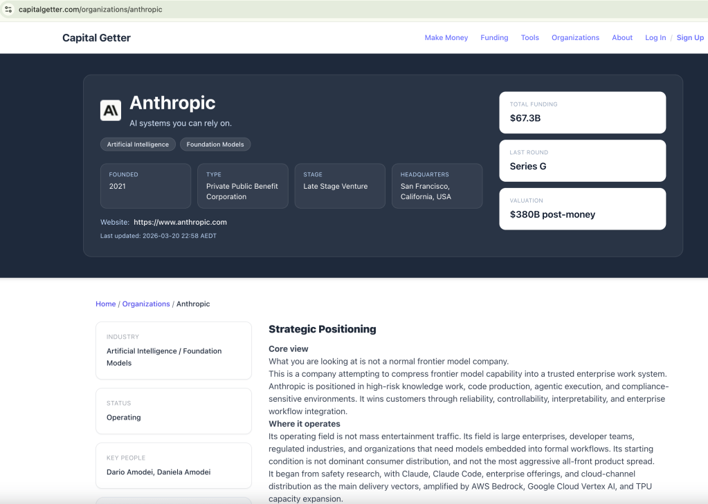
Sample JSON Output from calling business-strategic-analysis API
[ { "id": "strategic_positioning", "title": "**Strategic Positioning**", "markdown": "**Core view**\n\nWhat you are looking at is not a normal frontier model company.\n\nThis is a company attempting to compress frontier model capability into a trusted enterprise work system. Anthropic is positioned in high-risk knowledge work, code production, agentic execution, and compliance-sensitive environments. It wins customers through reliability, controllability, interpretability, and enterprise workflow integration.\n\n**Where it operates**\n\nIts operating field is not mass entertainment traffic. Its field is large enterprises, developer teams, regulated industries, and organizations that need models embedded into formal workflows. Its starting condition is not dominant consumer distribution, and not the most aggressive all-front product spread.\n\nIt began from safety research, with Claude, Claude Code, enterprise offerings, and cloud-channel distribution as the main delivery vectors, amplified by AWS Bedrock, Google Cloud Vertex AI, and TPU capacity expansion.\n\n**OpenAI contrast**\n\nBy contrast, OpenAI has pushed itself toward the shape of a general intelligence operating system: one side captures massive user and enterprise seats through ChatGPT, while the other expands capability into broader populations and use cases through deep research, agents, image, voice, and infrastructure programs.\n\nThe split between Anthropic and OpenAI is not about who can build models. It is about who is using which structure to consume the future value chain.\n\n**Bottom line**\n\nAnthropic wants to lock down high-trust, high-ACV, high-retention workflows first. OpenAI wants to occupy the cognition entry point, the work entry point, and the infrastructure entry point first." }, ...]
Closing
This is where applied AI becomes real.
Not at the point where a model can answer, but at the point where AI can be governed, integrated, released, audited, and operated inside real business workflows.
That is the gap I have been focused on closing.
I am based in Sydney. If your team is serious about applied AI, governed workflow systems, or enterprise AI architecture, feel free to reach out.